电 话:86-0769-88789588
传 真:86-0769-88788399
联系人:刘波 先生
手 机:13380195886
QQ:549528737
Skype:lacus_liu
Email:lacus_liu@vision-hk.com
邮 编:523039
网 址:
http://www.vision-hk.com
- 厂商: Young Chang Silicone Co.,Ltd
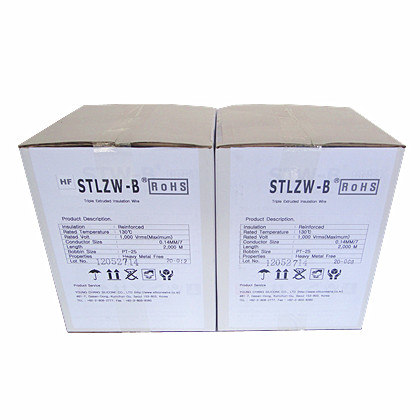
- 品牌: STLZW-B
1. APPLICATIONS
This specification is to be applied for Triple Insulated Litz Wire (SZW-B; hereinafter referred to as the "wire") using the winding or the wiring such as high-frequency operating electrical machine and apparatus.

2. STRUCTURE
2.1 CONDUCTOR
The conductor shall be used the enameled stranded copper wire specified in KS C 2611-1997 or JIS C 2529-1991.
2.2 INSULATION
The insulation covering shall consist of triple extruded layer (1st and 2nd layer: polyester type resin, 3rd layer: thermally reinforced polyamide) which are at least equivalent thereto in quality, extruded on the surface of the conductor uniformity. The insulation layers so applied shall have no detrimental effect to the conductor and shall show no flaws or dirt. Further, the wires shall be such that the soldering is possible without removing of the insulation layer. The wire shall be satisfied with B rated (130 °C) thermal index of IEC 172 and UL SUBJECT 2353 test condition.
2.3 COLOR
The color of the wire is basically yellow. Other colors are available on request.
3. CHARACTERISTICS
The characteristics of wire shall be satisfied with Appendix 2 value accordance with the requirements for Section 4. Other requirement of characteristics than those covered by this specification shall be as given in IEC 60950 3rd edition-1999 (Safety of information technology equipment including electrical business equipment) sub -clause 2.10.5.4 and Annex U. The rating voltage shall be 1,000Vrms and the insulation grade shall be the reinforced (withstand test voltage 3,000Vrms for 1min).
4. TEST
4.1 Appearance
Each winding wire shall be examined for scratch, contamination, crack and other harmful defects on the insulation by visual examination.
4.2 Dimension
The wire shall be measured the conductor diameter, insulation thickness and outer diameter as specified in KS C 3006-1986, 5 or JIS C 3003-1984, 5.
4.3 Spark Test
Final product shall be subjected to the spark test in accordance with the requirements for UL1581 Section 900. The test shall be performed at 3,000 Vrms.
4.4 Flexibility Test
Three samples are taken from a same lot of wire prepared in the manner described in below and tested at room temperature. A straight piece of wire at least 305 mm (12 inches) long is to be wound for 10 continuous carefully and adjacent turns around a polished mandrel of the diameter specified in Table 1. After winding, the specimen is to be examined for exposure of the base conductor or delamination by visual examination. There shall be no exposure of bare conductor, or delamination of the insulation.
After visual examination of the specimen, the sample is to be wound on the mandrel and subjected to electric strength tests at 3,000V for 1 min. The voltage shall be applied between the conductor and the mandrel.
Table 1 Mandrel diameter
noxssnoxss
|
Nominal conductor diameter |
Mandrel diameter, mm (inch) |
||
|
Mm |
Inch |
mm ± 0.2 mm |
inch ± 0.01 inch |
|
0.20~0.34 0.35~0.49 0.50~0.74 0.75~2.49 2.50~5.00 |
0.008~0.014 0.014~0.019 0.019~0.029 0.029~0.039 0.100~0.200 |
4.0 6.0 8.0 10.0 Four times the conductor diameter |
0.16 0.24 0.31 0.39 Four times the conductor diameters |
4-5. Dielectric Breakdown Voltage
Three samples are taken from a same Lot of wire prepared in the manner described in below and tested at room temperature.
A straight piece of the final wire construction, approximately 400 mm (16 inches) in length, with the insulation removed at both ends, is to be twisted back on itself for a distance of 125 ± 5 mm (5 ± 0.2 inches) with a load applied to the wire pair, and with the number of twists, as provided in loads applied to the wire pairs and number of twists, see Table 2.
The loop at the end of the twisted section is to be cut at two places to provide a maximum spacing between the cut ends. The wire is to be subjected to a test voltage, substantially sine-wave in form, having a frequency of 60 Hz. The voltage applied between the conductors of the wires shall be raised from zero to the prescribed voltage at a rate of 500 V per second and measure the breakdown voltage.
Table 2 Loads applied to the wire and number of twists
|
Nominal conductor diameter |
Load |
Number of twists |
||||
|
Over |
Up to an includingno |
N |
(lbf) |
|||
|
mm |
inch |
mm |
inch |
|||
|
0.100 |
0.004 |
0.250 |
0.009 |
0.85 |
0.19 |
33 |
|
0.250 |
0.009 |
0.355 |
0.014 |
1.70 |
0.38 |
23 |
|
0.355 |
0.014 |
0.500 |
0.019 |
3.40 |
0.76 |
16 |
|
0.500 |
0.019 |
0.710 |
0.027 |
7.00 |
1.57 |
12 |
|
0.710 |
0.027 |
1.060 |
0.041 |
13.50 |
3.03 |
8 |
|
1.060 |
0.041 |
1.400 |
0.055 |
27.00 |
6.06 |
6 |
|
1.400 |
0.055 |
2.000 |
0.078 |
54.00 |
12.14 |
4 |
|
2.000 |
0.078 |
2.500 |
0.098 |
108.00 |
24.27 |
3 |
4.6 Withstand Voltage
Two layered and three layered specimens are taken from a same Lot of wire prepared in the manner described in 4.5 Dielectric Breakdown Voltage Test and tested at room temperature.
Two layered wire shall be tested at 6,000V for 1 min and three layered wire shall be tested at 7,000V for 1 min.
4.7 Heat Shock Test
Three samples are taken from a same Lot of wire prepared in the manner described in below and tested at room temperature.
A straight piece of wire at least 305 mm (12 inches) long is to be wound for 10 continuous and adjacent turns around a polished mandrel of the diameter specified in the Table 2. The specimen is placed into an oven with forced air circulation for a period of 30 minutes and at a temperature within 5 °C (9° F) of the temperature specified in Table 3. After removal from the oven, the specimen is to be allowed to cool to room temperature, and after cooling is to be examined for cracks under a magnification level (wire diameter 0.04~0.50, magnification level 5~10; wire diameter up to 0.5, magnification level 0~6).
After visual examination of the specimen, the sample is to be wound on the mandrel and subjected to electric strength tests at 3,000V for 1 min. The voltage shall be applied between the conductor and the mandrel.